Modifying Parameters of Circuit Elements
There are parameter labels below the symbol of each element in a model. By default, the parameter labels are those traditionally associated with an element, e.g., C for a capacitor, R for a resistor, and so on.
If there is more than one element of a simple type in the model, the parameter labels include a number, i.e., R1, R2, R3,…
Make sure each parameter label is unique.
NOTE: If the parameter names are not unique, no error appears. The non-linear curve fitter treats parameters with the same name as one parameter. The fitter finds one value for each set of parameters that share a name.
Change the parameter names and the limits of an element by clicking the button associated with that circuit element.
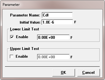
For example, if you click on a capacitor circuit element, you would get a Parameter window similar to that in the figure below.
Parameter Window

As you can see in the Parameter window, enter a new label for that parameter in the Parameter Name field if you wish. The Parameter Name is an alphanumeric string of up to 15 characters. In the figure above, the label was changed to Cdl, meaning double-layer capacitance. We recommend that you try to find descriptive names for your parameters.
The Initial Value field is the value which is first put into the fit dialog box. We recommend that you put in a number that would be most likely to be a good starting point for a fit. For example, for a solution resistance, an Initial Value of 50 Ω might be suitable.
The Lower Limit Test and Upper Limit Test areas give bounds for the parameter value in the curve fitter. In the figure above, the Lower Limit Test has been enabled with a boundary value of zero. This prevents the fitter from trying negative values for the parameter. This is a sensible thing to do, because a negative capacitor is an unlikely component to find in a real-world circuit model. Enabling the limit tests on parameters can speed up the curve-fitting process and help prevent non-convergence.

Comments are closed.