Common Physical Electrochemistry Setup Parameters
Each of the following are setup parameters common among the Physical Electrochemistry experimental techniques.
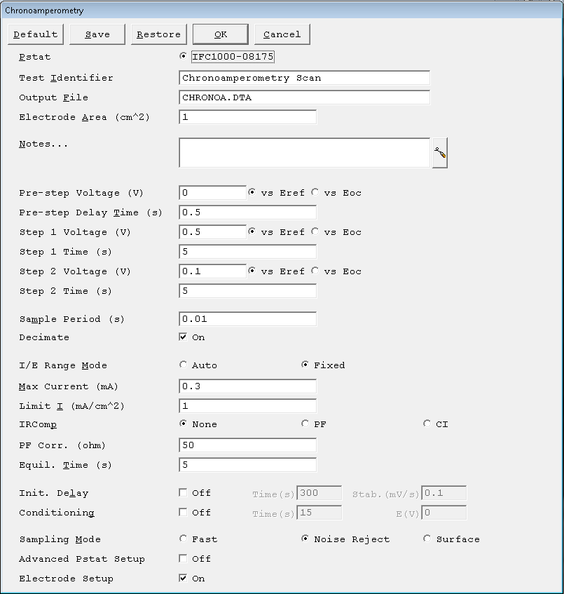
Pstat
- Selects which potentiostat/galvanostat performs the experiment. Each labeled button corresponds to an installed potentiostat. When a potentiostat is selected, its corresponding button is filled in. In a multiple potentiostat system you can change the potentiostat selection by clicking on a Pstat ’s button using the mouse. From the keyboard, tab down until a dotted line appears around one of the Pstat labels, then hit the space bar to select among the potentiostats. Only one potentiostat can be selected at a time, so selecting one potentiostat de-selects another one.
Test Identifier
- A string that identifies data. The Test Identifier parameter is written to the data file, so it can be used to identify data in database or data-manipulation programs.
- The Test Identifier string is also used as the title for both real-time plots and plots in the data-analysis software. The Identifier string defaults to a name derived from the technique’s name. While this makes an acceptable label for a curve, it does not generate a unique descriptive label for a data set.
- The Identifier string is limited to 80 characters. It can include all normally printable characters, including numbers, upper- and lower-case letters, and most normal punctuation including spaces.
Output File
- The pathname of the file in which the output data is written. It can be a simple filename with no path information. In this case the output file is located in the default data directory. The default data directory is specified in the Gamry.INI file under the [FRAMEWORK] section with a Key named DataDir. You can change this default pathname using Options > Path. It can also include path information, such as C:\DATA\YOURDATA.DTA. In this example, the data are written to the YOURDATA.DTA file in the DATA directory on drive C.
- The default value of the Output File parameter is an abbreviation of the technique name with a .DTA filename extension. We recommend that you use a .DTA filename extension for your data filenames. The data-analysis software assumes that all data files have .DTA extensions.
- NOTE: The software does not automatically append the “.DTA” filename extension. You must add it yourself.
- If the script is unable to open the file, an error message, Unable to Open File, appears. Common causes for this type of problem include:
- An invalid filename.
- The file is already open under a different Windows® application such as Excel®.
- The disk is full.
- After you click the OK button in the error box, the script returns to the Setup box where you can enter a new filename.
Electrode Area
- The surface area of the electrode (in cm²) exposed to the sample solution. If you do not wish to enter an area, leave this parameter at its default value of 1.0 cm².
Notes…
- Several optional lines of text that describe the experiment.
![]()
- Use Notes to record the experimental conditions for a data set. To the right of the Notes is a button to open the Experiment Notes window, shown below, which shows more. You can edit the notes in either place.
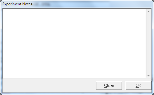
- Notes defaults to an empty string. The Notes string is limited to 400 characters, and includes all printable characters including numbers, upper- and lower-case letters, and most normal punctuation including spaces. Tab characters are not allowed.
- Divide your Notes into lines using enter.
Sample Area
- Surface area of the sample (in cm²) exposed to the solution and thus available to be corroded. The DC Corrosion system uses Sample Area or calculation of current density and the corrosion rate. If you do not want to enter an area, we recommend that you leave Sample Area at its defaultof 1.00 cm².
- NOTE: Do not enter a value of zero!
Init. Delay Time
- The Initial Delay phase of the experiment allows the open-circuit voltage of the sample to stabilize before the potential scan. The Delay Time is the time that the sample is held at open circuit prior to the scan. The delay may stop prior to the Delay Time if the Delay Stability criterion for Eoc is met (see below). The delay time parameter is active only if you have turned on Initial Delay in Setup. The units for Delay Time are seconds. The minimum time is one second, the maximum time is 400000 seconds (more than 4 days). Below 1000 seconds, the time resolution is one second. Between 1000 seconds and 10000 seconds, it is 10 seconds. Above 10000 seconds, it is 100 seconds.
IR Comp
- Gamry Instruments, Inc. potentiostats can estimate uncompensated voltage-drop caused by cell resistance. They do so by performing a current-interrupt measurement after every DC data point. Set the IR Comp checkbox to either On or Off. If the experiment uses potentiostatic control (e.g., potentiodynamic, Tafel, etc.) turning on IR Comp causes the applied E to be adjusted for the estimated IR-drop. If the experiment uses galvanostatic control, the measured E is adjusted for the estimated IR-drop.
Advanced Pstat Setup
- The Advanced Pstat Setup, if checked opens the Hardware Settings window, to control specific aspects about your hardware. If you are not an advanced user, or simply wish to use default hardware settings as specified in the scripts, just un-check this box. If, however, you wish to specifically set some hardware items, check this box. The Hardware Settings window apepars similar to the picture depicted below.

Electrode Setup
- The Electrode Setup checkbox, if checked, opens the Electrode Setup window, to control specific aspects about your electrode. If you are not an advanced user, or simply wish to use the default electrode settings, just un-check this box. If however, you need to specifically set the electrode type or stir/purge conditions, some hardware items, check this box and you will be presented with further options upon clicking the OK button. The Electrode Setup window looks similar to the picture depicted below.

The electrode types are:
| N/A | No special electrode |
| Solid | Solid-type electrode. |
| DME | Dropping Mercury Electrode |
| SMDE | Static Mercury Drop Electrode |
| HMDE | Hanging Mercury Drop Electrode |
| Rotating | Rotating Electrode – RDE or RRDE |
- If you select a Rotating electrode, an additional setup window appears.

- In this setup window you specify the Rotation Speed of the electrode. This speed is entered in Revolutions Per Minute (RPM). If you wish to stop the rotation at the end of the experiment, select the checkbox to turn off rotation after the experiment.
Comments are closed.