Drawing a Model Circuit
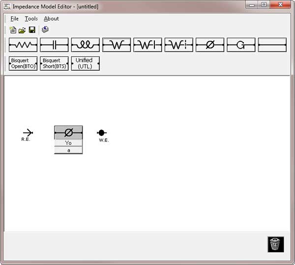
The lower portion of the model editor screen is blank except for two symbols labeled W.E. and R.E. This area is the drawing area. You draw the schematic diagram for your equivalent-circuit model in this blank area.
The symbol labeled W.E. is the working electrode terminal, and the symbol labeled R.E. is the reference electrode terminal. The model impedance is calculated as the impedance between these two terminals. All circuit elements must be directly or indirectly connected to each of these terminals. If they are not, a Wiring Error appears when the model is saved or compiled.
You can move the W.E. or R.E. terminal or any other circuit elements around in the drawing area. The moving process is called drag-and-drop. The terminals cannot be moved outside the drawing area and they cannot be discarded using the trash can icon.
To drag and drop a circuit element, point at it with the mouse and hold down the mouse button. A frame appears, which can be dragged around the windows as long as you hold down the mouse button. When you release the button, the component is redrawn (dropped) in the current location of the frame.

Add circuit elements to the model using the buttons above the drawing area. The above example shows a Constant Phase Element (CPE) added between the reference electrode and the working electrode. The CPE has two parameters associated with it: Y0 and a. Below are the meanings of the various element buttons:

Resistor

Capacitor

Inductor

Infinite Warburg

Bounded Warburg

Porous Warburg

Constant Phase Element

Gerischer
Wire
The impedance expressions for the first eight elements are given in the theory section. Wires are special circuit elements discussed later in this section.
When you click the button for an element, a copy of the element is added to the drawing. Initially the new element is located just below its button. The element includes a symbol and one or more buttons below the symbol. Drag and drop the newly created element to move it to its desired location.
In our example below, we will build a Randles cell model. We start by placing three circuit elements on the drawing area. After the elements are placed, a wire is created by clicking the wire button. The wire is below the button.
Wires differ from other components in several ways. They do not have an associated button. You drag and drop each end of the wire separately. When you are dragging one end of a wire you do not see a frame. Instead you see a small dark rectangle inside a slightly larger rectangular outline.
Wiring two elements together is quite simple. Drag one end of a wire to the first element to be connected. Drop this end of the wire on the small dot at the end of this element’s outline. Drag the second end of the wire to the second element to be connected, and drop it on its small dot. The wire should be aligned with the symbol in the element’s outline.

Comments are closed.