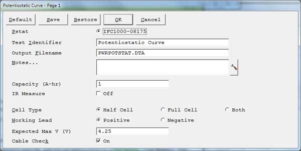
Potentiostatic Setup Parameters
Default button Restores all the parameters on the screen to their default values. Use it to fix typing errors or find out previous values for a parameter you have already retyped. The default values are the values as specified by the Explain™ script. All of the standard scripts perform an automatic restore of the last used values. These are the values first shown to the user. In order to get to the values specified by the script, use the Default button. Save button
Save the current parameter set on your disk. This is very useful when you are running repetitive tests. Parameter sets are stored in a file with a .SET file-name extension. More than one parameter set can be stored in each file, with the set distinguished by a Set Name. This system is a powerful tool for organizing your experimental setups. For example, each worker in a lab can have his own setup file (JOE.SET, KAREN.SET, etc.). Within her file, Karen can save multiple parameter sets under descriptive Set Names (C1010 Noise, Fast Noise, etc.).
Clicking Save opens a dialog box which requests the name of the file where you wish to save the parameter set, and the Set Name within in the file. Once you are satisfied with the names, clicking the OK button saves the set in the specified file.
Restore button Recovers a parameter set from your disk. This is useful when you are running repetitive tests. Clicking Restore opens a dialog box which requests the name of the file where your parameter set has been saved, and the Set Name within the file. Once you are satisfied with the names, clicking the OK button recalls the set from the specified file. Pstat Selects the potentiostat/galvanostat/ZRA to perform the experiment. Each labeled radio button corresponds to an installed potentiostat. When you choose a potentiostat, its corresponding radio button is filled in. In a multiple-potentiostat system, you can change the potentiostat selection by clicking on a Pstat’s radio button using the mouse. From the keyboard, tab down until a dotted line appears around one of the Pstat labels, then hit the space bar to select among the potentiostats. Only one potentiostat can be selected at a time, so selecting one potentiostat de-selects another one. Test Identifier
A string that is used as a name. It is written to the data file, so it can be used to identify the data in database or data manipulation programs.
The Identifier string defaults a name derived from the technique’s name. While this makes an acceptable curve label, it does not generate a unique descriptive label for a data set.The Identifier string is limited to 80 characters. It can include almost any normally printable character. Numbers, upper- and lower-case letters, and most normal punctuation characters including spaces are valid.
Notes
Enter several lines of text that describe the experiment. A typical use of Notes is to record the experimental conditions for a data set.
![]()
To the right hand side of the notes is a button. This button allows you to open the Experiment Notes dialog box, shown below, which shows more of the notes at one time.
You can edit the notes in either place.
Notes defaults to an empty string. The Notes string is limited to 400 characters. It can include all printable characters including numbers, upper- and lower-case letters, and the most normal punctuation including spaces. tab characters are not allowed in the Notes string. You can divide your Notes into lines using enter.
Output Filename
- The pathname of the file in which the output data are written. It can be a simple filename with no path information, where the output file is located in the default data directory. The default data directory is specified in the Gamry.INI file under the [Framework] section with a Key named DataDir. This default pathname can be changed using the Path command under the Options menu. It can also include path information, such as C:DATAYOURDATA.DTA. In this example, the data are written to the YOURDATA.DTA file in the DATA directory on drive C.
- The default value of the Output Filename parameter is an abbreviation of the technique name with a .DTA filename extension. We recommend that you use a .DTA filename extension for your data filenames. The data-analysis package assumes that all data files have .DTA extensions.
NOTE: The software does not automatically append the .DTA filename extension. You must add it yourself.
- If the script is unable to open the file, an error message box, Unable to Open File, appears. Common causes for this type of problem include:
- An invalid filename.
- The file is already open under a different Windows® application.
- The disk is full.
After you click the OK button in the error box, the script returns to the Setup box where you can enter a new filename.
Capacity
- Specifies the capacity—the amount of charge needed to charge or discharge a battery—to be recorded. This value is not used during the experimental phase, but rather during the analysis where a percent capacity graph can be displayed. The units for this parameter are ampere-hours (Ah).
Cell Type
- An optional parameter only displayed if a Reference 3000 or Interface 5000 is present.
- Half Cell radio button
- When the cell type is half-cell, the instrument measures the voltage between the working sense lead (blue) and the reference lead (white). This is the normal electrometer. The maximum measurable voltage in half-cell mode varies by instrument. See the manual for your instrument and the specifications for the electrometer.
- Full Cell radio button
- Full Cell mode is generally used to test a single-cell electrochemical device. The test assumes a two-electrode cell. The positive terminal of the cell is connected to the potentiostat’s working (green) and working sense (blue) leads. The negative terminal of the device is connected to the potentiostat’s counter (red) and reference (white) leads. The Electrochemical Energy software displays an error message if the Working Lead parameter is set to Negative. Connect the potentiostat’s counter sense (orange) lead to the cell cable’s ground (black) lead.
- Both radio button
- Both mode is only used for the Interface 5000 dual-electrometer mode. It measures the voltage difference between the reference lead (white) and both sense leads (blue and orange).
Working Lead
- Specifies how the potentiostat is connected to the electrochemical cell.
- When the working lead (green) is connected to the positive electrode (discharge cathode) of the electrochemical cell, select the Positive radio button for this parameter. When the working lead is connected to the negative electrode (discharge anode) of the electrochemical cell, select the Negative radio button for this parameter.
- In general, we recommend Positive.
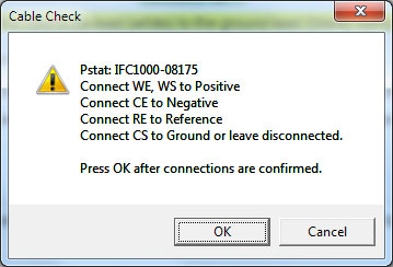
Cable Check checkbox
- If you activated this checkbox, the software warns you to confirm that your cable connections are appropriate for the selected Cell Type.
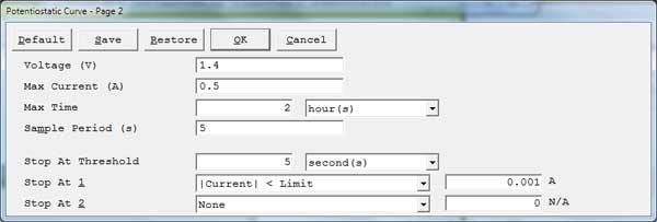
Voltage
- Specifies the constant potential applied to the cell. The value is specified involts (V).
Max Current
- Specifies the maximum current that is allowed to flow during the experiment.
-
To avoid overloading the instrument (so you can accurately track total charge passed), set this to a value below the instrument’s maximum current capabilities. Refer to the user’s manual to find the maximum current limit for your specific instrument.
Max Time
- Specifies the maximum amount of time to maintain the constant applied potential. The first field specifies the value. The value entered is based on the following drop-down list:
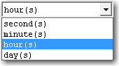
Select the appropriate units of time for the value entered in the edit box.
Sample Period
- The spacing between output data points. The units used for the Sample Period are seconds.
- The shortest Sample Period we recommend is 50.0 ms (0.05 s). The longest Sample Period allowed is 715 s (Reference models) or 750 s (Interface models).The number of data points must be less than 262143 (218 – 1).
Stop At Threshold
- The time tolerance of the Stop At conditions. A Stop At condition must be true for at least this duration of time before the experiment ends.
- For example, if Stop At Threshold is set to 5 seconds and Stop At 1 is set to |Voltage| > Limit of 4.2 V, the cell voltage must exceed 4.2 V for a minimum of 5 seconds for the experiment to end.
- Set Stop At Threshold to 0 seconds if you want the experiment to end immediately after a Stop At condition is met.
Stop At
- Allow you to specify various limits to an experiment. The limit, if met, causes the experiment to skip to the next step, or stop if there is no subsequent step.

Most experiments have Stop At 1 and Stop At 2. These parameters are treated equally, and if both are used, they are both tested on every raw data point. If either limit is reached, the experiment skips to the next step or stop.The available stop tests are shown in the drop-down list below.
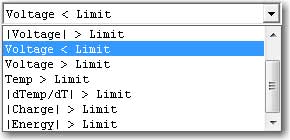
- Different experiments allow different tests, but the principles that govern their behavior are the same. After you choose a limit, the appropriate units for entry of the limit are shown to the side of the limit-value entry box as depicted below.
![]()
- When a voltage limit is selected, the entry units are volts. When a temperature limit is selected, the entry units are Celsius.
![]()
- The available stop tests are:
None
- No stop test specified. The experiment runs until the maximum specified time.
Voltage
- Voltage < Limit Stop if measured voltage is less than the value entered in V. Voltage > Limit Stop if the measured voltage is greater than the value entered in V. |Voltage| < Limit Stop if the absolute value of the measured voltage is less than the value entered in V.
- |Voltage| > Limit Stop if the absolute value of the measured voltage is greater than the value entered in V. |dV/dT| < Limit Stop if the absolute value of the measured voltage change rate is less than the value entered in V/s. |dV/dT| > Limit Stop if the absolute value of the measured voltage change rate is greater than the value entered in V/s.
Current
- Current < LimitStop if measured current is less than the value entered in A.
- Current > Limit Stop if the measured current is greater than the value entered in A.
- |Current| < Limit Stop if the absolute value of the measured current is less than the value entered in A.
- |Current| > Limit Stop if the absolute value of the measured current is greater than the value entered in A. |dI/dT| < Limit Stop if the absolute value of the measured current rate of change is less than the value entered in A/s.
- |dI/dT| > Limit Stop if the absolute value of the measured current rate of change is greater than the value entered in A/s.
Temperature
- Temp > Limit Stop if measured temperature is greater than the value entered in °C. |dTemp/dt| > Limit Stop if absolute value of measured temperature change is greater than the value entered in °C/min.
Charge and Energy
- |Charge| > Limit Stop if absolute value of accumulated charge is greater than the value entered in A-h.
- |Energy| > Limit Stop if absolute value of transferred energy is greater than the value entered in J.
IR Measure checkbox
- Determines whether or not the instrument performs IR measurements during the experiment. When performing an IR measurement, the flow of current is interrupted and the uncompensated resistance is determined based on the corresponding drop in the voltage measurement. Do not use this measurement with fast sample periods. As a general rule, any sample period faster than 1 second is too fast for IR measurement.The IR value is stored in a Vu column in the raw data file.
AE Channels
- An optional parameter that appears only if an instrument with the Auxiliary Electrometers option is present in the system. If you do not have an instrument with an AE option, you do not see this setup parameter. This parameter consists of checkboxes to select which channels are active during the experiment.
- Click the All button to select all of the channels.
- Click the None button to deselect all of the channels.
- In some experiments, there is a Set Limits checkbox. This checkbox opens a secondary AE Channel Limits window where limits for the individual AE channels can be entered, as seen here:
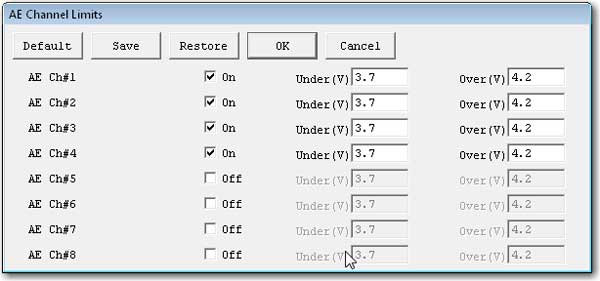
The checkbox for each AE channel turns the limit-checking on for that channel. The Under (V) parameter tests for voltages less than the entered value. The Over (V) parameter tests for voltages above the entered value. If the measured value on an AE channel exceeds one of these limits, the experiment skips to the next step, or end if there is no next step.
Comments are closed.