Description
Critical Pitting Temperature (CPT) includes three techniques that can be used in the study of pitting phenomena. These techniques are highly automated, with the computer completely controlling the data acquisition process.
Pitting Corrosion
The Critical Pitting Temperature system is used to determine the temperature-dependence of pitting corrosion. An electrochemical technique measures pitting while the temperature of a metal sample is varied. The pitting process is electrochemically accelerated, so you can get answers much more rapidly than with traditional exposure techniques.
•What do we mean by pitting corrosion?
Many electrochemical techniques assume a simplified model in which corrosion occurs uniformly over the entire metal surface. Unfortunately, many real-world systems undergo highly localized corrosion quite unlike the uniform corrosion model. Corrosion occurs in pits formed in the metal or in crevices where metal pieces are joined. The localized corrosion can cause an otherwise corrosion-free metal piece to fail. Stainless steels, high alloys, and aluminum are often subject to localized corrosion problems, especially in the presence of chloride ion or other active pitting agents.
•How does a pit form?
Pits normally are seen on metals that form passive films. For various reasons, the passive film breaks down in a small region of the metal surface. At this location, the metal anodically dissolves. The chemical products formed by the metal's dissolution hinder regrowth of the passive film, often via a local change in pH. As the metal continues to dissolve in the localized area, a pit forms in the metal surface. This pit traps yet more dissolution products, which further prevent repassivation. As a result, once a pit forms, it is self-sustaining. Pit growth can continue until the pit reaches completely through the metal.
The mechanism of crevice corrosion is very similar. Think of the crevice as a preformed pit trapping corrosion products and preventing repassivation.
There are two voltage parameters that are used to describe pitting behavior. The first is the critical pitting potential. Below the critical pitting potential, pits do not start. The second is the critical repassivation potential. Below this potential, pits that have already formed repassivate.
Localized corrosion phenomena often depend strongly on temperature. Often systems that do not undergo pitting attack at room temperature are pitted if the temperature is increased. Critical Pitting Temperature is used to describe the temperature at which pit initiation begins.
CPT System Overview
The following figure shows the block diagram for a Critical Pitting Temperature system that uses a TDC Temperature Controller. This figure is the basis of the following discussion.

A Gamry Instruments' Potentiostat/Galvanostat/ZRA (the system potentiostat) is connected to the host computer via USB. The system potentiostat's cell connector is attached directly to the electrochemical cell under test. You can use various cell designs. Gamry Instruments' Flex Cell Kit is a particularly useful cell because its unique design avoids the crevices found in other cell designs. This permits pitting to be studied without complications from crevice corrosion.
The temperature of the electrochemical cell is controlled by the TDC5 Temperature Controller. The TDC5 is a PID-controller able to maintain the cell's temperature to within 1°C. The cell temperature set points are all controlled via the RS-232/USB communications, which connect the TDC5 directly to the computer.
The cell temperature is measured by the TDC5 using a platinum RTD (Resistance Temperature Detector). The TDC5 sends the temperature to the computer. The system always checks that the requested temperature is reached before it takes a measurement. This closed-loop control allows experiments to be performed as rapidly as possible, without temperature errors.
In the above figure, a cartridge heater directly heats the cell. The TDC5 can also control a recirculating bath. The advantage of the bath is that it allows experiments to run below room temperature.
The Critical Pitting Test software runs in the system computer. It automates the control and data acquisition process.
Adding a Temperature Controller
|
The Gamry Framework™ installation program makes the appropriate entries into the GAMRY.INI file. Follow these steps only if you wish to make a change manually. |

|
If you need to setup the software for multiple temperature controllers, contact Gamry Instruments technical support or local representative. |
Open the GAMRY.INI file in any text editor.
For TDC4 Temperature Controllers
If you have a TDC4 Temperature Controller, add a new section of the form:
[TDC_1]
label = TDC4
port = X
mode = comX:2400,0,7,1
serialno = xxxxx
type = 4
In the above program code, X is the number of the COM port used to connect to the TDC4, e.g., COM2. When you type the lines, replace X with this number. The communications parameters are the default parameters for the TDC4.
For TDC5 Temperature Controllers
If you have a TDC5 Temperature controller, add a new section of the form:
[TDC_1]
label = TDC5
port = X
mode = comX:9600,N,8,1
serialno = xxxxx
type = 5
In the above program code, X is the number of the COM port used to connect to the TDC5, e.g., COM2. When you type the lines, replace X with this number. The communications parameters are the default parameters for the TDC5.
Check that the COM port shown in Device Manager matches what is in your *.INI file:
1.After the TDC5 is plugged into an available USB port on the host computer, turn on the host computer.
2.Log into your user account and run the Device Manager.
Expand the Ports section as shown.
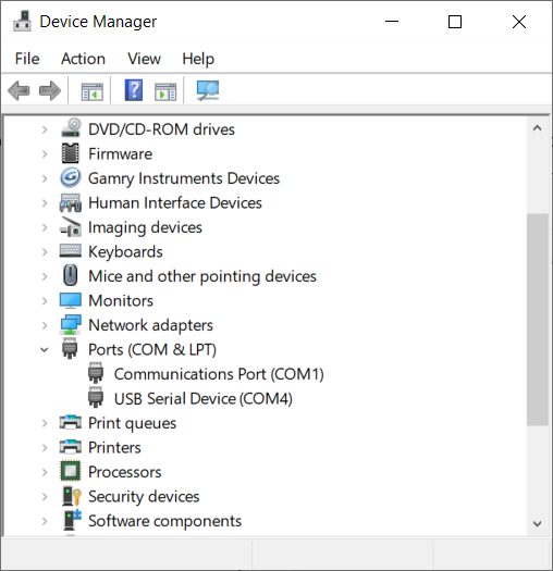
3.Turn on the TDC5 and look for a new entry that appears under Ports.
4.This entry will tell you the COM number associated with the TDC5. Take note of this for use during installation of the Gamry Instruments software.
5.If the COM port is higher than number 8, decide on a port number less than 8.
6.Right-click on the new USB Serial Device that appeared and select Properties.
The USB Serial Device Properties window like the one shown appears.
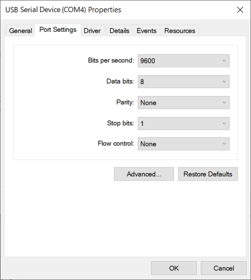
7.Select the Port Settings tab.
8.Click the Advanced… button. The Advanced Settings for COMx dialog box appears as shown. (Here x stands for the particular port number you have chosen.)
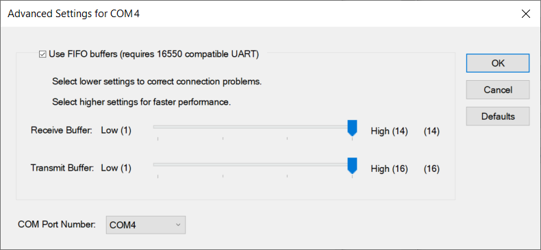
9.Select a new COM Port Number from the drop-down menu.
10.Select a number of 8 or less. You do not need to change any other settings.
11.Click the OK buttons on the two open dialog boxes to close them.
Calibrating the TDC
If your CPT system includes a TDC4 or TDC5 Temperature Controller, it needs to be calibrated before it can be used. Calibration instructions are in the TDC4 or TDC5 Operator's Manual.
|
Do not attempt the CPT check-up without calibrating the TDC4 or TDC5 first. |
System Check-up
The last step in the installation is a test to confirm that the system has been installed properly.
The following procedure tests a system based on a TDC5 temperature controller. It may work for third-party controllers, but Gamry Instruments does not guarantee this.
To test the operation of the system, run a simple checkout script provided with the Critical Pitting Temperature software. The name of this script is CHECK110.exp. Use the following procedure to check the system:
|
At each warning prompt, click the OK button or press the Enter key to proceed to the next step. |
1.Hook up an RTD probe to the and turn on the controller's power. After a few seconds, the upper display should register the temperature of the RTD.
2.Insert the probe into your electrochemical test cell. The cell may contain plain water. It must be equipped with a heater.
3.Put the controller into Manual Mode (you may need to push the Auto/Man button twice). The MAN LED illuminates.
4.Using the UP and DOWN keys on the controller, set the set-point temperature (lower display) to be equal to the process temperature (upper display).
5.Start Windows® and the Gamry Framework™.
6.Hook up the cell heater and cooling lines, or if the unit is to be used with a heating bath, make the rear panel connections to the bath.
7.Start the CHECK110.exp script:
a.Select Experiment > Named Experiment from the Framework menu bar.
b.In the dialog box, select CHECK110.exp and click the Open button.
8.Put the temperature controller into the Auto Mode by pushing the Auto/Man switch twice. The MAN LED turns off. The script will now set the controller set-point to the process temperature plus 5°C. The lower display should register the change.
9.Watch the upper display on the TDC5. It should report increasing cell temperatures. Watch the controller and verify that the heat control is cycling. If you do not wish to wait for the full temperature rise, select F2-Skip to continue to the next test.
10.The script now sets the controller set-point to the original process temperature. The lower display should register the change. Watch the upper display of the TDC5. It should report decreasing cell temperatures. If you don't have a cooling device on your cell, this may take a while. Check that the cooler is functioning. If you do not wish to wait for the full temperature decrease, select F2-Skip to go to the next test.
11.This completes the system checkout. Next you must tune your temperature controller for use with a specific system. See the temperature controller Operator's Manual for details concerning tuning.