Discharge Profile - Setup Parameters (page 2)

<< Click to Display Table of Contents >>

Navigation:  »No topics above this level«

Discharge Profile - Setup Parameters (page 2)

Description

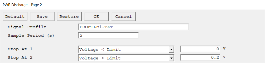
Second setup page of the Discharge Profile experiment. Press OK to continue or Cancel to go back to the first setup page.


G - PWR Discharge Profile - page 2


Parameter

Description

Units

Signal Profile

Applied current profile defined within a separate text file (*.txt). The file contains a single column of values which ArrayToVector loads into Framework. The values describe the current magnitude of each applied data point. The units are amperes (A), see example file below.


Gamry tip bulb

This file can be renamed and modified by the user to define the applied current profile. The *.txt file must be stored within the My Gamry Data directory.


Gamry tip bulb

Do not add a header or column label.

Do not add a time column. Time intervals are evaluated at the script level and determined by the Sample Period.


Sample Period

The spacing between data points. The shortest Sample Period we recommend is 0.5 s (50 ms). The longest Sample Period allowed is 715 s for Reference potentiostats and 750 s for Interface potentiostats.


seconds (s)

Stop At 1

Specify various limits to an experiment. Choose a limit criterion from the drop-down list and enter a limit value. The unit automatically updates according to the criterion. The limit, if met, causes the experiment to skip to the next step, or stop if there is no subsequent step.


Most experiments have Stop At 1 and Stop At 2 criteria. These parameters are treated equally, and if both are used, they are both tested on every raw data point. If either limit is reached, the experiment skips to the next step or stops entirely.


Gamry tip bulb

Different experiments allow different tests, but the principles that govern their behavior are the same.


Stop At 2


Related Topics