Description
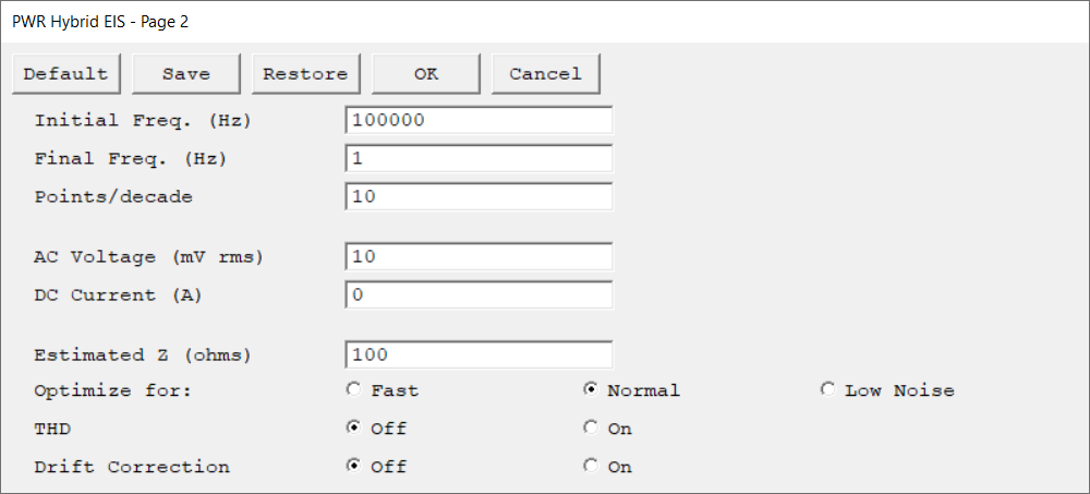
Second setup page of the Hybrid EIS experiment. Press OK to continue or Cancel to go back to the first setup page.
Parameter |
Description |
Units |
||
|---|---|---|---|---|
The starting frequency of the frequency sweep during data acquisition.
|
hertz (Hz) |
|||
The final frequency of the frequency sweep during data acquisition.
|
hertz (Hz) |
|||
The data density of the measured impedance spectrum. The data are spaced logarithmically and the number of data points in each frequency decade equals Points/decade. As a consequence, the frequency sweep may not stop exactly at the final frequency. It is guaranteed to do so only when the scan range contains an integer number of decades, such as 5 kHz to 0.05 Hz (five decades). You can use Initial Freq., Final Freq., and Points/decade to calculate the total number of data points in the spectrum.
|
|
|||
The amplitude of the desired AC Voltage signal which is measured at the cell. The applied current is changed to a value that should give the desired AC Voltage. Multiply the entered root-mean-square (rms) value by √2 (or ~1.414) to convert into a peak value.
|
mV rms |
|||
The constant current applied to the cell throughout the frequency sweep. The AC Current is summed with the DC Current. In most cases, the DC Current should remain at its default value of zero. The discussion of the AC Voltage describes some limitations on the DC Current value. |
mA |
|||
A user-entered estimate of the cell's impedance at the Initial Freq. parameter. It is used to limit the number of trials required before acquiring the first data point in an impedance spectrum. It is generally sufficient if Estimated Z is within a factor of five of the cell's impedance.
|
ohm |
|||
Select the sampling method for the experiment: •Fast is the appropriate selection when the cell's stability is poor and a spectrum must be measured rapidly, or the system's impedance is low and well defined. •Normal is the appropriate selection when the cell's impedance is high or the electrochemical system is noisy. •The best data can be taken with Low Noise, but the time required to record an EIS spectrum can be quite long.
|
|
|||
Enable Total Harmonic Distortion (THD) during the EIS experiment to obtain additional information about the system’s harmonics. |
|
|||
Select On to enable Drift Correction. Both the original and the drift-corrected impedance values are separately calculated and recorded. The drift corrected impedance plot will be active by default but can be changed from the drop-down menu above the chart.
Drift Correction fits current and voltage data to a sine wave using a linear drift term, followed by non-linear least squares regression. Drift data are then subtracted from the current and voltage values and the corrected impedance Z is calculated via Fourier analysis.
|
|
|||
An optional parameter that appears only if an instrument with the Auxiliary Electrometer option is connected. If your instrument does not include the AE feature, this configuration parameter will not be visible.
This parameter consists of checkboxes that allow to select which channels are active during the experiment. Click the All button to select, or None to deselect all channels.
There is a Set Limits checkbox available for some experiments. It opens a secondary AE Channel Limits window where limits for the individual AE channels can be entered. The checkbox for each AE channel turns the limit-checking on for that channel. The Under (V) parameter tests for voltages less than the entered value. The Over (V) parameter tests for voltages above the entered value. If the measured value on an AE channel exceeds one of these limits, the experiment skips to the next step or ends if there is no next step. |
|

