Description
The Aux Electrometer Calibration is only available for Reference™ 30x0s with the AE Option installed (and optional Reference™ 30k Booster). It corrects for voltage offsets and differences in the frequency response of the Auxiliary Electrometer (AE) channels.
|
You require the Auxiliary Electrometer Calibration fixture. If you do not have this fixture, you cannot perform the calibration. |

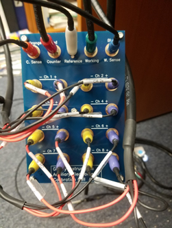
1.Connect the Auxiliary Electrometer Calibration fixture (see image below).
The top row of connections are the normal cell connections for Gamry Instruments users. The sixteen AE connections are clearly marked on the cables and the fixture.
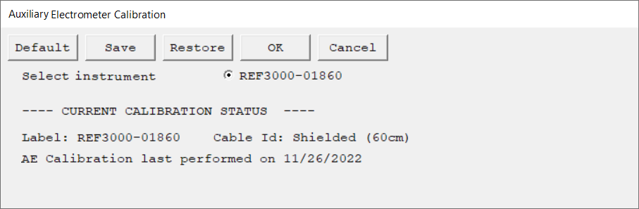
2.Run this calibration by selecting Experiment > Utilities > Aux Electrometer Calibration on the Framework menu bar. The dialog box opens:
|
The calibration script checks the connections before it makes the measurements used in Calibration. If you connect the cell fixture incorrectly, the software prevents incorrect calibration values. |
3.Calibration begins with voltage offset measurements. A series of voltage-versus-time curves appears. Out-of-range values generate Error Message dialog boxes.
4.After all DC Calibration tests are done, the calibration script performs AC Calibration of the AE Channels. A series of Lissajous figures appears. The AE has filters for each AE Channel, so the frequency response of the filters needs to be measured and corrected.
5.If the AE Calibration passes all tests, a Calibration Complete dialog box appears.