Description
Calibrate Cable Capacitance is used to measure correction values for EIS cable-capacitance correction. The correction eliminates EIS discontinuities caused by variations in cable-to-cable capacitance. The variation in capacitance occurs because of subtle differences in the materials and assembly procedures of individual cell cables. Differences in Work Lead-to-ground capacitance can cause phase and magnitude discontinuities when the instrument’s current range is changed in the middle of an EIS spectrum.
Starting with Revision 7.06 of Gamry Instruments’ Software Suite, all EIS data are corrected to eliminate the effects of this variation in capacitance. The correction is typically small; less than ±0.2% in magnitude and less than ±1° in phase.
|
We recommend you run the Calibrate Cable Capacitance procedure whenever you attach a different cell cable to your Gamry potentiostat. |

This calibration only requires a few clicks and keystrokes and you can run it in about one minute. The cable calibration stores calibration data in the instrument. You do not need to recalibrate when an instrument and cable are moved to a different location or connected to a different computer.
|
The calibration data stored for one specific cable may not be appropriate for a second cable, even though the cables may be the same type. |
Calibration process
1.Before starting an cable calibration, connect the Chassis Ground on the back of your potentiostat to a known, good earth ground.

Rear panel of the Interface 5000 potentiostat with the Chassis Ground connector highlighted.
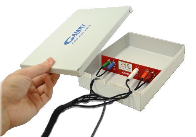
2.Connect the cell cable to the correct color-coded receptacles on the Calibration Cell. Place the Calibration Cell inside the Calibration Shield, close the lid, and connect the black floating ground lead of your cell cable to the Shield’s grounding post.
3.Run this calibration by selecting Experiment > Utilities > Calibrate Cable Capacitance on the Framework menu bar. The dialog box opens:
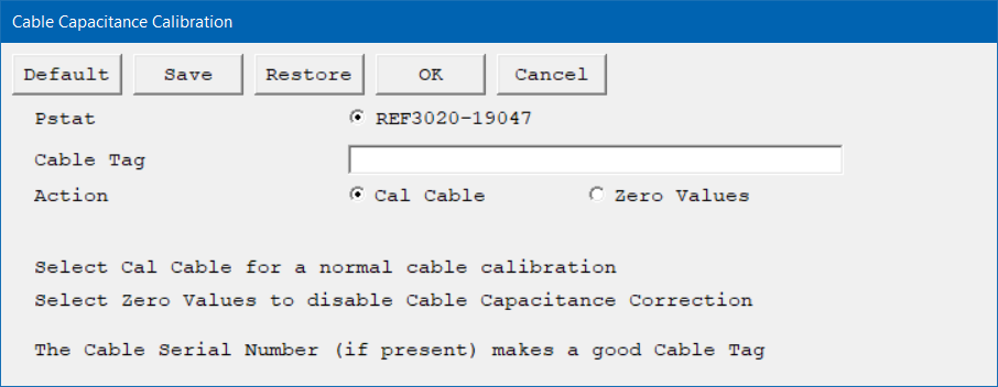
4.Select an instrument and enter all setup parameters.
Click the OK button to continue. The Performance Tips window appears.
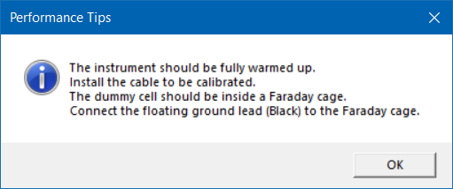
5.Make sure that all of the tips are true, then click the OK button.
The Cell Required window appears.
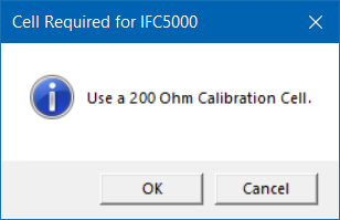
6.Make sure that the correct Calibration Cell is attached, then click the OK button.
The calibration runs.
|
For the best results, Gamry recommends using the calibration cell that was supplied with your potentiostat.
The Reference 600™ and Reference 600+™ cable calibrations require a 20 kΩ calibration cell. In these specific cases, Gamry Instruments has not already shipped you a suitable cell. Please contact Gamry Instrument support or local representative to purchase the required cell. |
If you do not have a calibration cell with the value requested, you can calibrate using a discrete axial-lead resistor. The resistor should be metal film or metal foil with ±1% (or better) tolerance. If you use a resistor you find in your laboratory, be careful with its connections and placement in the Faraday cage. Connect the Work and Work Sense (green and blue) to one end of the resistor and Counter, Counter Sense, and Reference (red, orange, and white) on the other end. The leads on one end should be at least 3 cm away from the leads on the other end. The Work and Work Sense leads and their end of the resistor should be at least 1 cm away from any surface (wall, bottom, or top) of the Faraday cage surrounding the calibration cell.
The real-time plots of two measured EIS spectra (plotted one after the other) appear. The software has automatically chosen the frequency range and amplitude used to measure these spectra. Different instruments and different cable types use different settings.
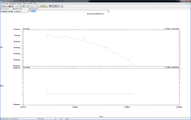
The first plot shows the non-corrected spectrum of the resistive cell; an example is given above. This spectrum is fit to a model containing two capacitances. The fit’s capacitances are stored in the instrument’s calibration table indexed by the Cable ID of the cable used in the calibration. The phase plot has units of millidegrees, so some noise is expected.
The second plot shows a corrected spectrum using the same settings, but with the Cable Capacitance Correction enabled using the new values.
7.The Done window appears when the calibration successfully finished. Click the OK button to confirm its completion.