Description
Parameter |
Description |
Units |
||
|---|---|---|---|---|
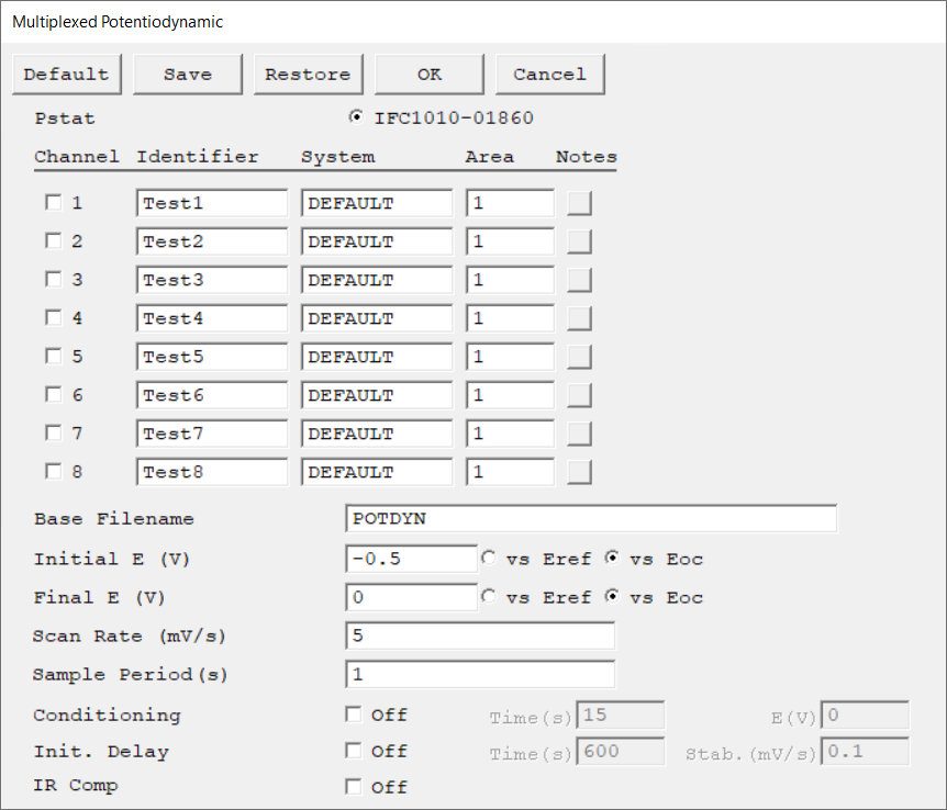
Select the potentiostat/galvanostat to perform the experiment. Each radio button corresponds to an installed potentiostat. You can select only one potentiostat at a time. Potentiostats that are already in use are marked with an asterisk. They can be selected but cannot be used.
|
|
|||
There is one Channel Setup switch for each of the 8 channels. Click the checkbox to select a specific channel. As the script loops through the channels, it only runs tests on channels that are selected. The selected channel numbers do not have to be continuous. |
|
|||
A string that is used as a name. It is written to the data file, so it can be used to identify the data in database or data manipulation programs.
The Channel Identifier string is virtually identical to the Test Identifier string. The only difference is that in multiplexed tests, the Identifier refers to an experiment run on a single cell and not to the entire experimental run. |
|
|||
Select a set of electrochemical parameters relevant to your particular test system. The parameters are recovered from the system parameter database file. The recovered parameters are all used for the calculation of the corrosion rate. They are the sample's equivalent weight, density, anodic β and cathodic β. When you attempt to run an experiment, the system searches the SYSTEM.SET file for a parameter set stored under the name in the System parameter. If the software finds no parameter set, an error message appears and you are returned to the Setup dialog box. |
|
|||
The electrode area that is used in calculations. It can be set individually for each channel. |
cm2 |
|||
Enter several lines of text that describe the experiment. There is a separate entry for each channel in a multiplexed test. A typical use of Channel Notes is to record the experimental conditions for a data set.
The Channel Notes controls are similar to the Notes control described for non-multiplexed experiments. |
|
|||
Each channel has its own data file. The Base Filename is used to derive the filenames for these files. The filename for Channel N (1–8) is created by appending the character N to the Base Filename, then adding a *.DTA filename extension.
|
|
|||
The starting potential of the potential sweep during data acquisition. The allowed range is ±10 V with a resolution of 0.125 mV. Its accuracy is determined by the settings of Initial E and Final E.
|
volts (V) |
|||
The final potential of the potential sweep during data acquisition. The allowed range is ±10 V with a resolution of 0.125 mV. Its accuracy is determined by the settings for Initial E and Final E. |
volts (V) |
|||
The speed of the potential sweep during data acquisition.
|
mV/s |
|||
The spacing between data points. The shortest Sample Period we recommend is 0.1 s. The longest Sample Period allowed is 715 s for Reference potentiostats and 750 s for Interface potentiostats.
|
seconds (s) |
|||
You may condition the electrode as the first step of the experiment, e.g., to remove an oxide film from the electrode or to grow one. Conditioning ensures that the metal sample has a known surface state at the start of the experiment. This step is done potentiostatically for a set amount of time.
|
seconds (s), volts (V) |
|||
Use the Initial Delay parameter to tell the system your definition of a stable potential and when to begin the actual measurement. If the absolute value of the Eoc drift-rate falls below the Stability parameter, the Initial Delay phase ends immediately and the experiment begins, disregarding the Time parameter. The drift rate can never fall below zero, so entering a Stability value of zero ensures that the Initial Delay will not end prematurely. A typical value is 0.05 mV/s. The lower limit of the Stability parameter is set by your patience. For example, a stability of 0.01 mV/s indicates a drift of less than 1 mV within 100 seconds. |
seconds (s), mV/s |
|||
Choose to turn iR-compensation either On or Off. Turning on IR Comp causes the applied potential to be adjusted for the estimated iR-drop.
Gamry potentiostats are able to estimate uncompensated voltage-drop caused by cell resistance. They do so by performing a current-interrupt experiment after every data point. |
|

