Description
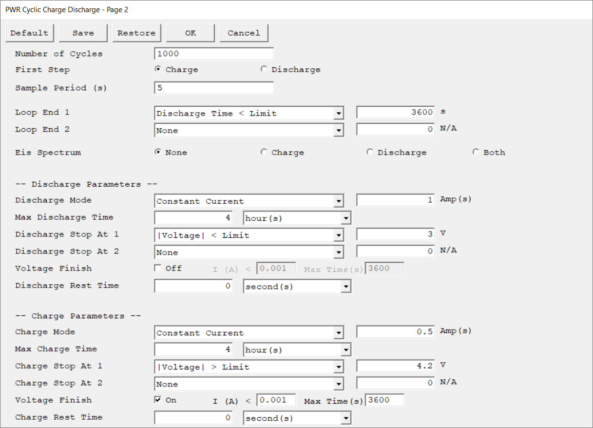
Second setup page of the Cyclic Charge Discharge experiment. Press OK to continue to the third setup page or Cancel to go back to the first setup page.
Parameter |
Description |
Units |
|||||||||||||||||||||||||||||||||||
|---|---|---|---|---|---|---|---|---|---|---|---|---|---|---|---|---|---|---|---|---|---|---|---|---|---|---|---|---|---|---|---|---|---|---|---|---|---|
Specify the number of charge-discharge cycles. Each cycle consists of one charge step and one discharge step. |
|
||||||||||||||||||||||||||||||||||||
Decide whether the first step of a cyclic charge-discharge experiment is a charge or discharge step. |
|
||||||||||||||||||||||||||||||||||||
The spacing between data points. The shortest Sample Period we recommend is 0.5 s (50 ms). The longest Sample Period allowed is 715 s for Reference potentiostats and 750 s for Interface potentiostats.
|
seconds (s) |
||||||||||||||||||||||||||||||||||||
Terminate the repeating experiment when a conditional test becomes TRUE. In a Cyclic Charge Discharge experiment, a Loop End test is typically used to stop the experiment when the device has lost most of its capacity or fails to charge. |
|
||||||||||||||||||||||||||||||||||||
|
|||||||||||||||||||||||||||||||||||||
Add EIS measurements to the cyclic charge-discharge experiment (if the potentiostat is EIS capable). If enabled, additional EIS parameters can be set on the third setup page: •None No EIS measurement. •Charge / Discharge EIS measurements are only performed after charge or discharge steps respectively. •Both EIS measurements are performed after both charge and discharge steps. |
|
||||||||||||||||||||||||||||||||||||
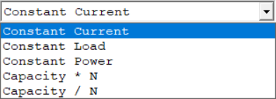
Use the drop-down list to specify the mode for the discharge step. There are five modes available: Constant Current, Constant Load, Constant Power, Capacity * N, and Capacity / N.
Enter the value for the selected mode. The units are specified by each mode. Capacity * N and Capacity / N use the C-rate, in units of #N.
|
|
||||||||||||||||||||||||||||||||||||
Specify the maximum time of the experiment. The first field specifies the value. Select the unit from the drop-down list. |
seconds (s), minutes (min), hours (hr), days (d) |
||||||||||||||||||||||||||||||||||||
Specify various limits to an experiment. Choose a limit criterion from the drop-down list and enter a limit value. The unit automatically updates according to the criterion. The limit, if met, causes the experiment to skip to the next step, or stop if there is no subsequent step.
Most experiments have Stop At 1 and Stop At 2 criteria. These parameters are treated equally, and if both are used, they are both tested on every raw data point. If either limit is reached, the experiment skips to the next step or stops entirely.
|
|
||||||||||||||||||||||||||||||||||||
|
|||||||||||||||||||||||||||||||||||||
Primarily used for the charging of batteries. When the battery has reached a voltage limit, it is held at the voltage limit for the user-specified time, or until the current has dropped below a user-specified limit.
The checkbox is used to turn the voltage finish ON and OFF. The first field specifies the lower current limit at which the voltage finish terminates. The second field specifies the maximum duration the voltage is applied, if the current limit is never reached.
|
amperes (A), seconds (s) |
||||||||||||||||||||||||||||||||||||
The Charge and Discharge Rest Time setup parameters make the system sit idle at the charged or discharged state for the specified time. The experiment continues with the next step after the specified time has elapsed. |
seconds (s), minutes (min), hours (hr), days (d) |
||||||||||||||||||||||||||||||||||||
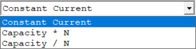
Use the drop-down list to specify the mode for the charge step. There are three modes available: Constant Current, Capacity * N, and Capacity / N.
Enter the value for the selected mode. The units are specified by each mode. Capacity * N and Capacity / N use C-rate, in units of #N. |
|
||||||||||||||||||||||||||||||||||||
Specify the maximum time of the experiment. The first field specifies the value. Select the unit from the drop-down list. |
seconds (s), minutes (min), hours (hr), days (d) |
||||||||||||||||||||||||||||||||||||
Specify various limits to an experiment. Choose a limit criterion from the drop-down list and enter a limit value. The unit automatically updates according to the criterion. The limit, if met, causes the experiment to skip to the next step, or stop if there is no subsequent step.
Most experiments have Stop At 1 and Stop At 2 criteria. These parameters are treated equally, and if both are used, they are both tested on every raw data point. If either limit is reached, the experiment skips to the next step or stops entirely.
|
|
||||||||||||||||||||||||||||||||||||
Primarily used for the charging of batteries. When the battery has reached a voltage limit, it is held at the voltage limit for the user-specified time, or until the current has dropped below a user-specified limit.
The checkbox is used to turn the voltage finish ON and OFF. The first field specifies the lower current limit at which the voltage finish terminates. The second field specifies the maximum duration the voltage is applied, if the current limit is never reached.
|
amperes (A), seconds (s) |
||||||||||||||||||||||||||||||||||||
The Charge and Discharge Rest Time setup parameters make the system sit idle at the charged or discharged state for the specified time. The experiment continues with the next step after the specified time has elapsed. |
seconds (s), minutes (min), hours (hr), days (d) |
||||||||||||||||||||||||||||||||||||
An optional parameter that appears only if an instrument with the Auxiliary Electrometer option is connected. If your instrument does not include the AE feature, this configuration parameter will not be visible.
This parameter consists of checkboxes that allow to select which channels are active during the experiment. Click the All button to select, or None to deselect all channels.
There is a Set Limits checkbox available for some experiments. It opens a secondary AE Channel Limits window where limits for the individual AE channels can be entered. The checkbox for each AE channel turns the limit-checking on for that channel. The Under (V) parameter tests for voltages less than the entered value. The Over (V) parameter tests for voltages above the entered value. If the measured value on an AE channel exceeds one of these limits, the experiment skips to the next step or ends if there is no next step. |
|