Description
Parameter |
Description |
Units |
||
|---|---|---|---|---|
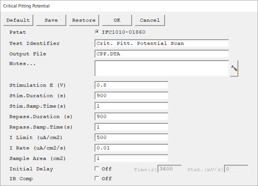
Select the potentiostat/galvanostat to perform the experiment. Each radio button corresponds to an installed potentiostat. You can select only one potentiostat at a time. Potentiostats that are already in use are marked with an asterisk. They can be selected but cannot be used. |
|
|||
A string that is used as a name. It is written to the data file, so it can be used to identify the data in database or data manipulation programs. The Identifier string defaults to a name derived from the technique's name. While this makes an acceptable curve label, it does not generate a unique descriptive label for a data set. The Identifier string is limited to 80 characters. It can include almost any normally printable character. Numbers, upper- and lower-case letters, and the most common punctuation characters including spaces are valid. |
|
|||
The name of the file in which the output data are written. By default, it is saved in the default file directory.
|
|
|||
Enter several lines of text that describe the experiment. A typical use of Notes is to record the experimental conditions for a data set.
Notes defaults to an empty string and is limited to 400 characters. It can include all printable characters including numbers, upper- and lower-case letters, and the most common punctuation including spaces. Tab characters are not allowed in the Notes string. Press the Notes button on the right-hand side to open a separate Notes dialog box. |
|
|||
The potential applied to the specimen during the Stimulation phase of the experiment. The allowed range is ±10 V with a resolution of 0.125 mV. |
volts (V) |
|||
The maximum duration of the stimulation phase. The script proceeds to the next phase of the experiment if the current has not exceeded the limit by this time. |
seconds (s) |
|||
The maximum length of the Repassivation phase. The Repassivation phase stops early if I Limit is reached or if I Rate is exceeded. |
seconds (s) |
|||
The spacing between data points during the Stimulation phase. The smallest recommended sample time is 0.25 s. We recommend sampling times between 0.5 and 1 s.
The Sample Time, along with the Duration, determine the number of data points in a phase. No more than 65 000 data points are allowed in each phase. You can calculate the Number of Points from:
The current-versus-time curves from all phases are stored in one data file. With ten or more curves recorded in a single experiment, the data file can become very large. You can keep the data file size manageable by recording fewer curves or storing fewer data points in the curves.
The CPP system can handle 255 curves, each containing 65 000 data points. However, the time required for the analysis software to load such a file may be astronomical. |
seconds (s) |
|||
The current at which you are satisfied that the specimen is pitting. If at any point during the Stimulation phase the current exceeds this limit, the experiment continues with the next Repassivation phase. The experiment stops if the current exceeds this limit during the Repassivation phase. |
μA/cm2 |
|||
The rate-of-change in current at which you are satisfied the specimen is pitting.
This parameter is used only in the Stimulation phase. If the derivative of the current-versus-time curve exceeds this limit for 20 seconds, the script stops the Stimulation phase and switches to the next Repassivation phase.
Disable the I Rate test by entering a very large value. For example, try using an unrealistically large I Rate of 1E10 µA. |
μA/cm2 |
|||
The surface area of the sample that is exposed to the solution. The software uses the sample area to calculate the current density and corrosion rate (if applicable). If you do not want to enter an area, we recommend that you leave it at the default value of 1.00 cm².
|
cm2 |
|||
Use the Initial Delay parameter to tell the system your definition of a stable potential and when to begin the actual measurement. If the absolute value of the Eoc drift-rate falls below the Stability parameter, the Initial Delay phase ends immediately and the experiment begins, disregarding the Time parameter. The drift rate can never fall below zero, so entering a Stability value of zero ensures that the Initial Delay will not end prematurely. A typical value is 0.05 mV/s. The lower limit of the Stability parameter is set by your patience. For example, a stability of 0.01 mV/s indicates a drift of less than 1 mV within 100 seconds. |
seconds (s), mV/s |
|||
Choose to turn iR-compensation either On or Off. Turning on IR Comp causes the applied potential to be adjusted for the estimated iR-drop.
Gamry potentiostats are able to estimate uncompensated voltage-drop caused by cell resistance. They do so by performing a current-interrupt experiment after every data point. |
|

