Description
Parameter |
Description |
Units |
||
|---|---|---|---|---|
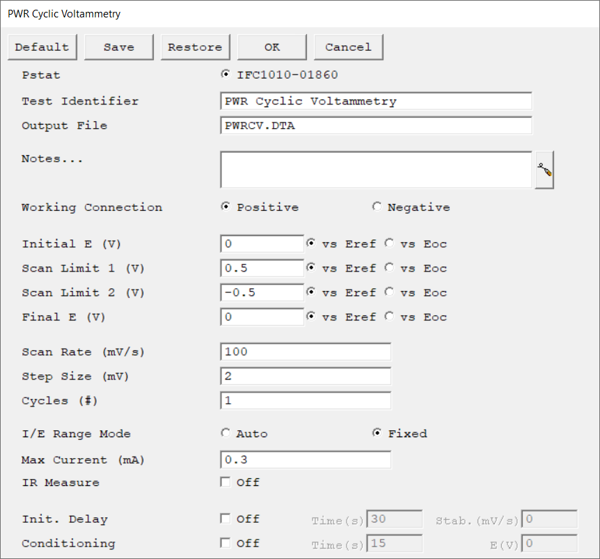
Select the potentiostat/galvanostat to perform the experiment. Each radio button corresponds to an installed potentiostat. You can select only one potentiostat at a time. Potentiostats that are already in use are marked with an asterisk. They can be selected but cannot be used. |
|
|||
A string that is used as a name. It is written to the data file, so it can be used to identify the data in database or data manipulation programs. The Identifier string defaults to a name derived from the technique's name. While this makes an acceptable curve label, it does not generate a unique descriptive label for a data set. The Identifier string is limited to 80 characters. It can include almost any normally printable character. Numbers, upper- and lower-case letters, and the most common punctuation characters including spaces are valid. |
|
|||
The name of the file in which the output data are written. By default, it is saved in the default file directory.
|
|
|||
Enter several lines of text that describe the experiment. A typical use of Notes is to record the experimental conditions for a data set.
Notes defaults to an empty string and is limited to 400 characters. It can include all printable characters including numbers, upper- and lower-case letters, and the most common punctuation including spaces. Tab characters are not allowed in the Notes string. Press the Notes button on the right-hand side to open a separate Notes dialog box. |
|
|||
Specify how the potentiostat is connected to the electrochemical cell.
Select Positive when the working lead (green) is connected to the positive electrode (discharge cathode) of the electrochemical cell. Select Negative when the working lead (green) is connected to the negative electrode (discharge anode) of the electrochemical cell.
|
|
|||
The starting potential of the scan segment. The potential can be specified versus the open-circuit potential (vs. Eoc) or reference electrode potential (vs. Eref). |
volts (V) |
|||
The first apex potential of the scan segment. Enter the potential either versus the reference electrode potential (vs. Eref) or open-circuit potential (vs. Eoc). |
volts (V) |
|||
The second apex potential of the scan segment. Enter the potential either versus the reference electrode potential (vs. Eref) or open-circuit potential (vs. Eoc). |
volts (V) |
|||
The final potential of the scan segment. The potential can be specified versus the open-circuit potential (vs. Eoc) or reference electrode potential (vs. Eref).
The scan segment stops at this value if Scan Limit 2 and Final E are equal. |
volts (V) |
|||
The speed of the potential sweep during data acquisition.
|
mV/s |
|||
The spacing between the data points. A typical Step Size setting is between 1 and 5 mV. Use the Step Size parameter and the Scan Range on any given cycle to determine the number of data points:
The total number of data points must be less than 64 000 for all cycles. |
mV |
|||
The number of times the scan is repeated during the experiment.
Conceptually, it is the number of times the potential cycles from the Initial E setting to Scan Limit 1 to Scan Limit 2 to the Final E setting. |
|
|||
Select the current range mode and choose between Auto mode or Fixed mode.
If set to Auto mode, the I/E Range changes depending on the measured current to optimize the current resolution/error. Auto-ranging does not work well for very small currents or faster sample periods. Do not use Auto mode with sample periods faster than ~1 s.
|
|
|||
Max Current controls the current measurement range if I/E Range is set to Fixed mode. If I/E Range is set to Auto mode, Max Current specifies the maximum expected starting current. |
mA |
|||
Determine whether or not to perform IR-measurements during the experiment. When performing an IR-measurement, the current is interrupted and the uncompensated resistance is determined based on the corresponding drop in the voltage measurement. The IR-value is stored in the Vu column of the raw data file.
|
|
|||
The Initial Delay phase of the experiment is the first step to occur in the experimental sequence. This phase of the experiment stabilizes the open-circuit potential of the sample prior to any applied signal and measures that open-circuit potential.
|
seconds (s), mV/s |
|||
You may condition the electrode as the first step of the experiment, e.g., to remove an oxide film from the electrode or to grow one. Conditioning ensures that the metal sample has a known surface state at the start of the experiment. This step is done potentiostatically for a set amount of time.
|
seconds (s), volts (V) |

