Description
Parameter |
Description |
Units |
||
|---|---|---|---|---|
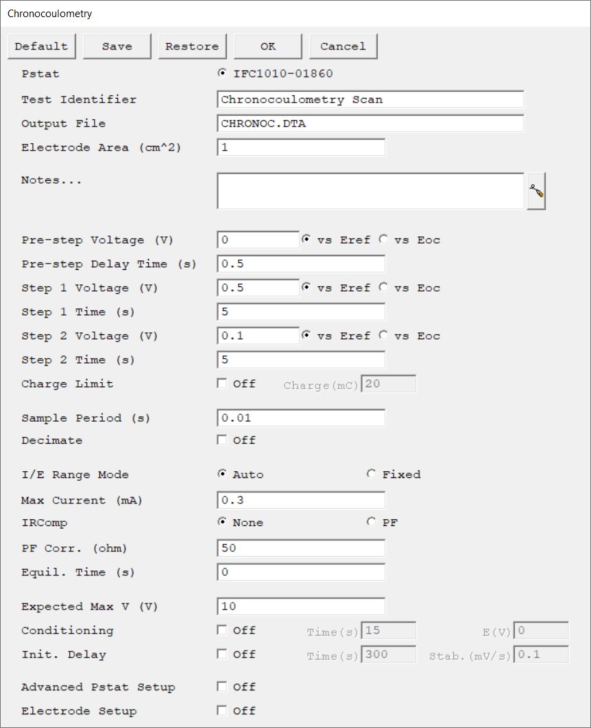
Select the potentiostat/galvanostat to perform the experiment. Each radio button corresponds to an installed potentiostat. You can select only one potentiostat at a time. Potentiostats that are already in use are marked with an asterisk. They can be selected but cannot be used. |
|
|||
A string that is used as a name. It is written to the data file, so it can be used to identify the data in database or data manipulation programs. The Identifier string defaults to a name derived from the technique's name. While this makes an acceptable curve label, it does not generate a unique descriptive label for a data set. The Identifier string is limited to 80 characters. It can include almost any normally printable character. Numbers, upper- and lower-case letters, and the most common punctuation characters including spaces are valid. |
|
|||
The name of the file in which the output data are written. By default, it is saved in the default file directory.
|
|
|||
The surface area of the sample that is exposed to the solution. The software uses the sample area to calculate the current density and corrosion rate (if applicable). If you do not want to enter an area, we recommend that you leave it at the default value of 1.00 cm².
|
cm2 |
|||
Enter several lines of text that describe the experiment. A typical use of Notes is to record the experimental conditions for a data set.
Notes defaults to an empty string and is limited to 400 characters. It can include all printable characters including numbers, upper- and lower-case letters, and the most common punctuation including spaces. Tab characters are not allowed in the Notes string. Press the Notes button on the right-hand side to open a separate Notes dialog box. |
|
|||
The voltage applied in the pre-step before the Step 1 Voltage is applied. Enter the voltage either versus the reference electrode potential (vs. Eref) or open-circuit potential (vs. Eoc). |
volts (V) |
|||
The duration of the pre-step when the Pre-step Voltage is applied. |
seconds (s) |
|||
The voltage applied in the first voltage step. Enter the voltage either versus the reference electrode potential (vs. Eref) or open-circuit potential (vs. Eoc). |
volts (V) |
|||
The duration of the first voltage step when Step 1 Voltage is applied. |
seconds (s) |
|||
The voltage applied in the second voltage step. Enter the voltage either versus the reference electrode potential (vs. Eref) or open-circuit potential (vs. Eoc).
|
volts (V) |
|||
The duration of the second voltage step when Step 2 Voltage is applied. |
seconds (s) |
|||
The Charge Limit prevents excessive cell charge if turned on. If the absolute value of the charge exceeds Charge Limit, data acquisition stops and the cell is turned off. |
|
|||
The spacing between data points. The shortest Sample Period we recommend is 0.1 s. The longest Sample Period allowed is 715 s for Reference potentiostats and 750 s for Interface potentiostats.
|
seconds (s) |
|||
Enable this option to display the time on a logarithmic scale during the experiment. |
|
|||
Select the current range mode and choose between Auto mode or Fixed mode.
If set to Auto mode, the I/E Range changes depending on the measured current to optimize the current resolution/error. Auto-ranging does not work well for very small currents or faster sample periods. Do not use Auto mode with sample periods faster than ~1 s.
|
|
|||
Max Current controls the current measurement range if I/E Range is set to Fixed mode. If I/E Range is set to Auto mode, Max Current specifies the maximum expected starting current. |
mA |
|||
Prevents excessive cell current. If the absolute value of the current exceeds Limit I, data acquisition stops and the cell is turned off.
Exceeding the Limit I at the Initial E step causes the potential to be skipped. The experiment will be terminated if the current exceeds Limit I at the Final E step. |
mA/cm2 |
|||
Choose to turn iR-compensation either On or Off. Turning on IR Comp causes the applied potential to be adjusted for the estimated iR-drop.
Gamry potentiostats are able to estimate uncompensated voltage-drop caused by cell resistance. They do so by performing a current-interrupt experiment after every data point. |
|
|||
The resistance compensated for with positive feedback (PF) selected under IRComp. This value should be between 80–95% of the uncompensated resistance Ru. You cannot compensate for 100% with PF IRComp enabled. |
ohm |
|||
The duration during which the cell remains at the initial potential, with the cell turned on before data acquisition begins. It allows the system to equilibrate before the actual experiment starts. No data are recorded during this step.
|
seconds (s) |
|||
The maximum expected voltage which sets the initial voltage measurement range and voltage offset of the galvanostat. If necessary, the voltage measurement range is adjusted during the signal-optimization phase, but this adds extra time to the experiment. |
volts (V) |
|||
You may condition the electrode as the first step of the experiment, e.g., to remove an oxide film from the electrode or to grow one. Conditioning ensures that the metal sample has a known surface state at the start of the experiment. This step is done potentiostatically for a set amount of time.
|
seconds (s), volts (V) |
|||
The Initial Delay phase of the experiment is the first step to occur in the experimental sequence. This phase of the experiment stabilizes the open-circuit potential of the sample prior to any applied signal and measures that open-circuit potential.
|
seconds (s), mV/s |
|||
Select the sampling method for the experiment. Depending on the experiment type, choose between Fast, Noise Reject, and Surface mode. |
|
|||
The Advanced Pstat Setup checkbox, if checked, opens the Hardware Settings window, to control specific aspects about your hardware. If you are not an advanced user or simply wish to use the default hardware settings as specified in the scripts, just un-check this box. If you wish to specifically set some hardware items, check this box. The Hardware Settings window opens upon clicking the OK button. |
|
|||
The Electrode Setup checkbox, if checked, opens the Electrode Setup window, to control specific aspects about your electrode. If you are not an advanced user, or simply wish to use the default electrode settings, just un-check this box. If you need to specifically set the electrode type, the stir/purge conditions, or some hardware items, check this box. The Electrode Setup window opens upon clicking the OK button. |
|

