Description
Differential Pulse Stripping Voltammetry (DPS) is an extension of the Differential Pulse Voltammetry technique. It works identically to Differential Pulse Voltammetry except it includes an “accumulation” step.
In the accumulation step, analytes are plated or otherwise accumulated on the electrode. Typically, the accumulation is done for tens or hundreds of seconds. The accumulated material is then removed (stripped) from the electrode quickly. Accumulating analyte on the electrode increases the mass of material available for the electrochemical reaction. Currents are higher, so the level of detection falls dramatically. In some systems, Sampled DC Stripping Voltammetry can achieve sensitivity in the parts-per-trillion (ppt) range.
You can plot and analyze the data files from this test with Gamry’s Echem Analyst 2™.
Setup Parameters
The setup for Differential Pulse Stripping Voltammetry adds two input parameter to the setup for Differential Pulse Voltammetry - Setup Parameters. These new parameters are Conditioning and Accumulation Time.
|
The accumulation phase of the test is done at Initial E. In a typical stripping voltammetry test this is a voltage where analytes plate onto the electrode surface. You therefore must choose an Initial E where this will occur. |

|
The accumulation phase must have reproducible transport of the analyte to the electrode surface. We strongly recommend stirring whenever the accumulation time is greater than 3 s. If you do not stir, random vibration in the lab environment will lead to extremely poor run-to-run reproducibility. Most electrochemical cells can be used with a magnetic stirrer and a stir bar in the electrolyte. |
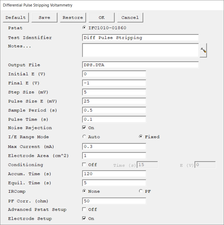
Parameter |
Description |
Units |
||
|---|---|---|---|---|
Select the potentiostat/galvanostat to perform the experiment. Each radio button corresponds to an installed potentiostat. You can select only one potentiostat at a time. Potentiostats that are already in use are marked with an asterisk. They can be selected but cannot be used. |
|
|||
A string that is used as a name. It is written to the data file, so it can be used to identify the data in database or data manipulation programs. The Identifier string defaults to a name derived from the technique's name. While this makes an acceptable curve label, it does not generate a unique descriptive label for a data set. The Identifier string is limited to 80 characters. It can include almost any normally printable character. Numbers, upper- and lower-case letters, and the most common punctuation characters including spaces are valid. |
|
|||
Enter several lines of text that describe the experiment. A typical use of Notes is to record the experimental conditions for a data set.
Notes defaults to an empty string and is limited to 400 characters. It can include all printable characters including numbers, upper- and lower-case letters, and the most common punctuation including spaces. Tab characters are not allowed in the Notes string. Press the Notes button on the right-hand side to open a separate Notes dialog box. |
|
|||
The name of the file in which the output data are written. By default, it is saved in the default file directory.
|
|
|||
The starting potential of the scan segment. This potential is specified versus the reference electrode potential (vs. Eref). |
volts (V) |
|||
The final potential of the scan segment. This potential is specified versus the reference electrode potential (vs. Eref). |
volts (V) |
|||
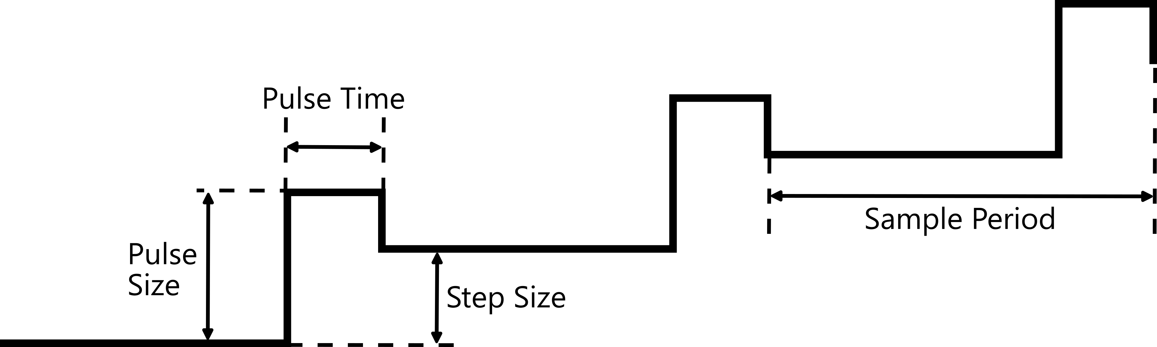 |
mV |
|||
mV |
||||
seconds (s) |
||||
seconds (s) |
||||
Specify how a measurement is taken. When Noise Rejection is off, a single point is taken for the measurement. When Noise Rejection is on, data points are taken and averaged for the duration of a line cycle. The line cycle is either 50 or 60 Hz. The speed at which data acquisition is taken varies based on the instrument used. PC5 family potentiostats take data at a rate of 33.333 µs/sample. |
|
|||
Select the current range mode and choose between Auto mode or Fixed mode.
If set to Auto mode, the I/E Range changes depending on the measured current to optimize the current resolution/error. Auto-ranging does not work well for very small currents or faster sample periods. Do not use Auto mode with sample periods faster than ~1 s.
|
|
|||
Max Current controls the current measurement range if I/E Range is set to Fixed mode. If I/E Range is set to Auto mode, Max Current specifies the maximum expected starting current.
The software adjusts the current range based on the Max Current input. In order to use the most sensitive range that will not overload, the software chooses the current range based on a value that is 89% of the full-scale current range.
|
mA |
|||
The surface area of the sample that is exposed to the solution. The software uses the sample area to calculate the current density and corrosion rate (if applicable). If you do not want to enter an area, we recommend that you leave it at the default value of 1.00 cm².
|
cm2 |
|||
You may condition the electrode as the first step of the experiment, e.g., to remove an oxide film from the electrode or to grow one. Conditioning ensures that the metal sample has a known surface state at the start of the experiment. This step is done potentiostatically for a set amount of time.
|
seconds (s), volts (V) |
|||
The potential of the working electrode is maintained at the Initial E for the specified time. |
seconds (s) |
|||
The duration during which the cell remains at the initial potential, with the cell turned on before data acquisition begins. It allows the system to equilibrate before the actual experiment starts. No data are recorded during this step.
|
seconds (s) |
|||
Choose the type of iR-compensation to be used during data acquisition. There are two settings: •None: No iR-compensation is performed. •PF: Positive-feedback iR-compensation takes a user-entered correction value (PF Corr.) which corrects for the uncompensated resistance. Because this value is entered at the beginning of the experiment and not measured after every point, this compensation method is suitable for fast experiments. |
|
|||
The resistance compensated for with positive feedback (PF) selected under IRComp. This value should be between 80–95% of the uncompensated resistance Ru. You cannot compensate for 100% with PF IRComp enabled. |
ohm |
|||
The Advanced Pstat Setup checkbox, if checked, opens the Hardware Settings window, to control specific aspects about your hardware. If you are not an advanced user or simply wish to use the default hardware settings as specified in the scripts, just un-check this box. If you wish to specifically set some hardware items, check this box. The Hardware Settings window opens upon clicking the OK button. |
|
|||
The Electrode Setup checkbox, if checked, opens the Electrode Setup window, to control specific aspects about your electrode. If you are not an advanced user, or simply wish to use the default electrode settings, just un-check this box. If you need to specifically set the electrode type, the stir/purge conditions, or some hardware items, check this box. The Electrode Setup window opens upon clicking the OK button. |
|
