Calibrate Cable Capacitance
Introduction
Calibrate Cable Capacitance is used to measure correction values for EIS cable-capacitance correction. The correction eliminates EIS discontinuities caused by variations in cable-to-cable capacitance. The variation in capacitance occurs because of subtle differences in the materials and assembly procedures of individual cell cables. Differences in Work Lead-to-ground capacitance can cause phase and magnitude discontinuities when the instrument’s current range is changed in the middle of an EIS spectrum.
Starting with Revision 7.06 of Gamry Instruments’ Software Suite, all EIS data are corrected to eliminate the effects of this variation in capacitance. The correction is typically small; less than ±0.2% in magnitude and less than ±1° in phase.
NOTE: We recommend you run the Calibrate Cable Capacitance procedure whenever you attach a different cell cable to your Gamry potentiostat.
This calibration only requires a few clicks and keystrokes and you can run it in about one minute.
The cable calibration stores calibration data in the instrument. You do not need to recalibrate when an instrument and cable are moved to a different location or connected to a different computer.
The data stored for one specific cable may not be appropriate for a second cable, even through the cables may be the same type.
Procedure
Run Calibrate Cable Capacitance by selecting Experiment > Utilities > Calibrate Cable Capacitance on the Framework™ menu.
A Cable Capacitance Calibration dialog box similar to this appears:
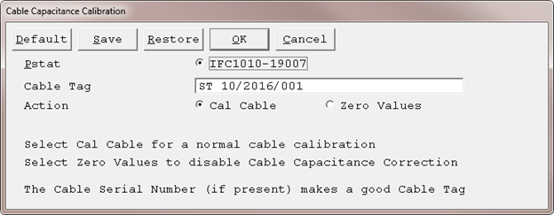
Pstat radio button Choose one potentiostat in a multi-potentiostat system. (In the example above, the only potentiostat in the system is selected.) Cable Tag field
Name the results of the calibration. In the example above, the serial number printed on a label near the D-connector end of a cable was entered in this field. Most Gamry Instruments cables shipped since mid-2016 have a similar serial number. You can enter other text in this field, but the cable serial number is a unique identifier. One advantage of using this number: you can read this number from the cable and compare it to the instrument’s calibration history.
The calibration results are stored in a file with a name that contains this Cable Tag. The slash characters (/) used in the cable serial number is not valid in a filename, so they (and all other punctuation marks) are converted into hyphens (-) before the filename is generated.
Action area
•Choose the Cal Cable radio button to measure the capacitance characteristics of your potentiostat and cell cable. Recorded values are saved in the instrument and used for cable capacitance correction.
•Choose the Zero Values radio button to remove any previously-stored capacitance values.
NOTE: Only use Zero Values if you suspect Cable Capacitance Correction is not working properly on your experiments.
After choosing all above functions, click the OK button.
If you chose Cal Cable, a Performance Tips window like this appears:

Confirm that all the advisory information is correct, and click the OK button. A Cell Required window like this appears:
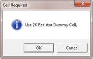
For best results, Gamry recommends you use the calibration cell (built on a printed circuit board) that was supplied with your potentiostat.
NOTE: The Reference™ 600+ and Reference™ 600 cable calibrations require a 20 kΩ calibration cell. In these specific cases, Gamry Instruments has not already shipped you a suitable cell.
If you do not have a calibration cell with the value requested, you can calibrate using a discrete axial-lead resistor. The resistor should be metal film or metal foil with ±1% (or better) tolerance. If you use a resistor you find in your laboratory, be careful with its connections and placement in the faraday cage. Connect the Work and Work Sense (green and blue) to one end of the resistor and Counter, Counter Sense, and Reference (red, orange, and white) on the other end. The leads on one end should be at least 3 cm away from the leads on the other end. The Work and Work Sense leads and their end of the resistor should be at least 1 cm away from any surface (wall, bottom, or top) of the faraday cage surrounding the calibration cell.
You may contact Gamry Instruments customer support at techsupport@gamry.com or your local Gamry representative to get the required cell. There may be a small cost.
Connect the requested resistive cell and click the OK button. The real-time plots of two measured EIS spectra (plotted one after the other) appear. The software has automatically chosen the frequency range and amplitude used to measure these spectra. Different instruments and different cable types use different settings.
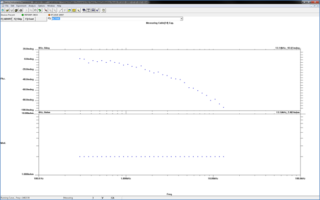
The first plot shows the non-corrected spectrum of the resistive cell; an example is given above. This spectrum is fit to a model containing two capacitances. The fit’s capacitances are stored in the instrument’s calibration table indexed by the Cable ID of the cable used in the calibration. The phase plot has units of millidegrees, so some noise is expected.
The second plot shows a corrected spectrum using the same settings, but with the Cable Capacitance Correction enabled using the new values.
At the end of the calibration, a Done message box appears:
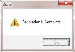
Click the OK button to complete the calibration.
A record of the calibration process is stored in a text file in the folder that contains your Gamry results (normally My Gamry Data). The file contents are usually not very interesting. The file name and the date it was created are useful. The file name for the calibration run above is:
Cable Calibration IFC1010_19007_CID14_ST07-2017-009.txt
If you look for these text files in your My Gamry Data folder, you can see the last cable that was calibrated on your system and the potentiostat used for its calibration.
Comments are closed.