Theory behind Cable-Capacitance Correction
Stray Elements as a Source of EIS Errors
EIS measures the impedance of an electrochemical cell over a wide range of frequencies. Often EIS measurements suffer from errors caused by “stray” electrical elements that are not a part of the cell. Stray elements arise from interactions of a cell connection with its environment, with the potentiostat electronics, and with other connections. Stray resistance, stray inductance, and stray capacitance can all cause errors in the measurement of cell impedance. This Help page concerns only one stray element: capacitance between the system’s Working Electrode (and its cell cable lead) and the potentiostat’s measurement ground.
The Effect of Stray Capacitance from the Working Electrode to Ground
Gamry Instruments’ potentiostats use a circuit topology with the Working electrode connected to ground through a current-range resistor. This scheme is relatively immune to stray capacitance between the Counter electrode and ground. Any current that flows through a capacitor from the counter Electrode to ground is not measured as cell current.
The trade-off to this approach is that stray capacitance between the Working electrode and ground is in parallel with the current-measurement resistor, Rm. This produces frequency-dependent error, because some of the AC cell current does not flow through Rm.
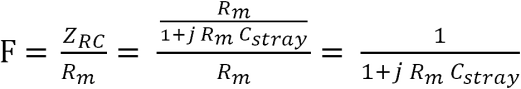
The complex impedance ZRC of a capacitor Cstray in parallel with resistor Rm is given by:
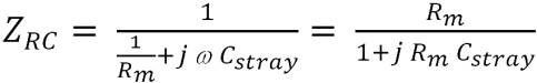
The error factor F in the current measurement is the ratio ZRC divided by Rm.
The ideal cell impedance Zcell is the ratio of cell voltage Vcell divided by the cell current Icell.
Zcell = Vcell/Icell
In the ideal case, Icell is calculated using the measured voltage across Rm (called VRM) divided by Rm.
Icell = VRM/Rm
Combining the last two equations, the ideal cell impedance is given by:
Zcell = (Vcell • Rm) / VRM
The measured cell impedance Zm is in error by the reciprocal of the error factor F.
Zm = Zcell / F = Zcell (1 + j RmCstray) = Zcell + j RmZcellCstray
Cell-Cable Variation causes Capacitance Variation
One source of capacitance across Rm is in the cell cable that connects your Gamry Instruments potentiostat to the electrochemical cell. To avoid noise pickup, the Working electrode lead is a coaxial cable, with the coaxial shield connected to ground. The capacitance of Gamry Instruments’ standard cell cables is between 30 pF and 3 nF, depending on the specific type and length of cable.
Gamry Instruments’ EIS software knows that this capacitance exists, and corrects for its effects. The standard correction flattens the measured EIS response for one specific cable attached to one specific potentiostat. While it does not explicitly use the last equation from the previous section in its corrections, it implicitly corrects for the effects of cable capacitance across Rm.
Problems occur with this form of EIS correction because different cables of the same length and type have different Working-electrode lead capacitances. The differences come from manufacturing variation in the coaxial cable and small variations in the geometry of the cable terminations.
Gamry Instruments’ EIS corrections, without cable-capacitance correction, assume that all cables are identical to the cable used for EIS calibration at Gamry Instruments’ factory. When the actual cell cable has a different capacitance, the system’s EIS response reveals show frequency-dependent errors. In an experiment that switches current ranges during measurement of an EIS spectrum, these errors appear as EIS discontinuities at the frequency where the current-range switches. The discontinuity is generally more visible in phase, but there are errors in both phase and magnitude.
Correcting for Cable-Capacitance Variation
Gamry’s cable-capacitance correction is a small correction in impedance data that removes the errors caused by variations in cable capacitance.
When you connect a new cable to a Gamry Instruments potentiostat, run a calibration called Calibrate Cable Capacitance. This calibration measures two capacitance values, roughly equivalent to the capacitance of the cable currently attached to the potentiostat, and the capacitance of the cable originally used in EIS Calibration. The term roughly is used, because the exact capacitance values are unimportant; the values are calculated to provide optimal correction for the cable currently attached to the potentiostat. The capacitance values measured during Calibrate Cable Capacitance are stored within the potentiostat’s non-volatile memory.
The cable-capacitance correction is applied to all EIS impedances measured using the calibrated system. The correction takes the form:

where Z is the corrected impedance, Zm is the uncorrected complex impedance value, Rm is the current range resistor used to measure Zm, ω is the radial frequency of the measurement, and j is √–1.
As mentioned above, ideally C1 is the capacitance of the cell cable in use and C0 is the capacitance of the cell cable used for factory EIS calibration. The cable-capacitance correction is still valid if C0 and C1 differ from these “ideal” definitions.
NOTE: Cable-capacitance correction uses calibration data generated in the Calibrate Cable Capacitance procedure. If you change cables and do not rerun this procedure, the EIS corrections will be incorrect and EIS data collected on the system may show discontinuities.
The plot below shows two EIS spectra measured on a 2 kΩ calibration cell using the same instrument, cable, and cell. The plot resembles a Bode plot but with linear magnitude and highly magnified y and yʹ axes. The magnification shows details not seen in typical Bode plots.
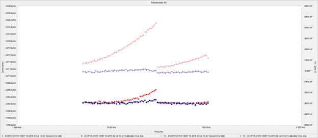
The red spectrum has no cable-capacitance correction. An EIS discontinuity occurs at 30 kHz, where the instrument’s current range switches between the 10 µA and 100 µA current ranges. The blue spectrum was recorded with the same cell cable after calibration.
The phase discontinuity after correction is approximately 12 millidegrees.
Comments are closed.