Uncompensated Resistance
Electrochemical test cells always have a solution resistance controlled by the cell’s geometry and the composition of the cell’s electrolyte. Current flow through this solution resistance can cause significant errors in the cell’s measured potential.
A three-electrode potentiostat compensates some of the cell’s solution resistance through placement of the cell’s reference electrode. Because reference electrodes are not infinitely small and they cannot be placed infinitely close to the working electrode, this compensation is always incomplete. The portion of the total solution resistance that is left uncompensated is called Ru(uncompensated resistance).
You can use positive feedback iR-compensation to correct for the effects of Ru—if you know the Ru value. In essence, positive feedback iR-compensation circuitry, at a desired potential Ed, applies a potential Ed + iRu (where i is the measured cell current). With this voltage applied between the working and reference electrodes, the electrochemical interface at the working electrode has a potential of Ed.
Unlike some other iR-compensation methods, ideally current feedback iR-compensation is fast, quiet, dynamically corrects for the iRu error as the cell current changes, and the actual voltage applied to the electrode interface is the same as the potentiostat’s input voltage.
However, there are at least two problems with positive feedback iR-compensation:
- You must determine or calculate the value of Ru before you can apply the method.
- Excessive compensation can cause instability and oscillation in the potentiostat’s electronics.
The Utilities menu includes a script that uses Electrochemical Impedance Spectroscopy (EIS) to make a determination of Ru. The script name is GetRu.EXP. You start it from the Framework™ by selecting Experiment > Utilities > Get Ru.
When the GetRu.EXP script runs, you select a potential, and the EIS determination is made at that potential. Carefully select this potential. In general, the potential used for Ru determination should be free from electrochemical reactions. In most systems 0 V vs. Eoc(open-circuit potential) has no interference from reactions.
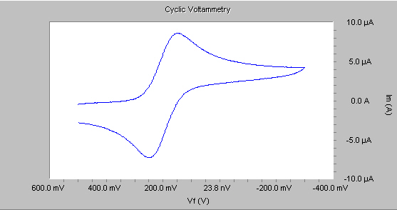
For example, the figure below shows the Cyclic Voltammogram of ferrocyanide on a platinum electrode in 0.1 M KCl. Notice the reduction peak beginning at +0.3 V vs. SCE. Above this voltage, we see no faradaic current. We recommend that you make the Ru determination in this system at 0.5 V vs. SCE.
In EIS, a small sinusoidal voltage is applied to the cell. The resulting current should be a sinusoid at the same frequency, but different amplitude and phase. If the cell impedance at the applied voltage and frequency is primarily resistive, the phase-angle between the voltage and current should be nominally zero. Phase-angles significantly more positive than zero indicate onset of potentiostat speed limitations or inductive behavior in the cell. Phase-angles significantly below zero are characteristic of capacitive, kinetic, or diffusional control of the cell impedance.
Ideally, measure Ru at the highest frequency at which the phase-angle of the cell impedance is zero degrees. At this frequency, Ru is the “real” portion of the cell impedance.
Note that many systems have a quite low Ru value, indicating that iR-compensation is not required. The system shown in the figure above had a measured Ru of about 8 Ω. A typical CV current in this system was 10 µA. At this current, the error in the applied voltage in the absence of iR-compensation is 80 µV. In general, ignore iR errors less than 1 mV, as in this case.
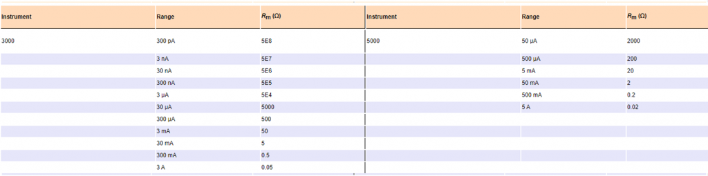
The range and resolution of the positive feedback iR-circuit is limited. Assume for the moment that you need positive feedback iR-compensation for a cyclic voltammetry (CV) experiment. CV is normally done using a fixed current measurement range. There is an equivalent current measurement resistance associated with each range. This resistance is known as Rm.

In general, avoid entering the full measured Ru value into tests that use positive feedback iR-compensation. A potentiostat is likely to oscillate when fully iR-compensated. We recommend that 75 to 95% of the measured Ru value be applied as compensation. In our example system, with an 8 Ω Ru, the positive feedback value, if entered at all, would therefore be entered as a value between 6 Ω (at 80% compensation) or 7.6 Ω (at 95% compensation)
Comments are closed.